Engineering project
Edge Mill Machine – Reverse Engineering & Spiral Line Mill Design
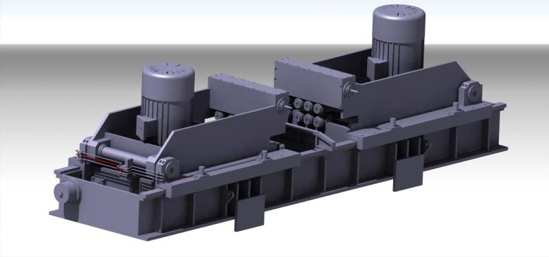
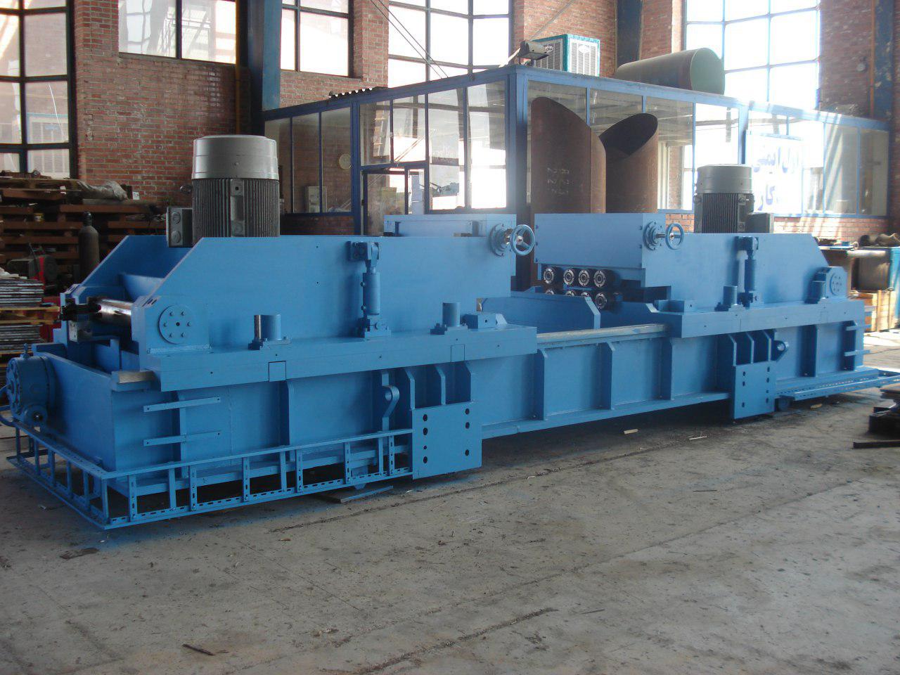
Project Code: PRJ-EMM-SPRL-RE
Objective
Reverse engineering and technical redocumentation of a precision edge mill machine used for longitudinal edge beveling in spiral pipe production lines. The goal was to replicate and document the full machine structure for domestic manufacturing in absence of original design files.
Problem Statement
The machine—originally sourced from abroad—was installed at Safa Rolling Complex (FREYMAN – Mashhad, Iran) without any accompanying technical documentation. The client required complete disassembly, modeling, and drawing of the entire machine based solely on physical inspection and manual measurements under real-world shop-floor conditions.
My Role
- Project Lead for disassembly, modeling, and documentation
- Manual measurement and inspection of all components
- Complete 3D modeling in CATIA V5
- Creation of fabrication and assembly drawings with tolerances
- Supervised junior team members and validated subcomponents
-
Delivered full technical package including:
- ~800 modeled parts
- Assembly layouts, exploded views, and shop-ready manufacturing drawings
Note: Although not involved in fabrication, hands-on work with real machinery gave me deep insights into tolerancing and manufacturability that no screen-only design experience could offer.
Machine Specifications
- Application: Longitudinal edge beveling of steel plates for spiral pipe welding
- Maximum plate width: 2500 mm
- Machine dimensions: ~1000 × 1000 × 1000 mm
- Number of parts modeled: ~800
- Subsystems included:
- Base frame and chassis
- Gearboxes and roller units
- Forming and guiding frames
- Mechanical supports and alignment systems
Technical Details
- Software Used: CATIA V5
- Project Duration: ~3 months
- Design Standards Applied:
- ISO 2768-mK – General tolerancing
- ISO 1101 – GD&T
- ASME Section IX / ISO 13920 – Welding standards
- Measurement Tools: Calipers, micrometers, dial gauges (manual)
Process Overview
- Disassembled and manually measured each machine component on-site
- Logged all dimensions into categorized spreadsheets
- Reconstructed full 3D assemblies in CATIA
- Generated 2D manufacturing and assembly drawings with full BOM
- Verified consistency through digital mockup and cross-checked fit points
Challenges and Insights
- No reference documents: Tolerances inferred using functional logic and engineering judgment
- Manual-only measurement: Increased complexity but enhanced dimensional reasoning
- Young team and no simulation tools: Required real-time decision-making and high attention to detail
Results
- Complete technical documentation delivered to client
- Enabled domestic production and future maintenance of strategic equipment
- Workflow structure reused in similar reverse engineering projects
- Strengthened my ability to lead multi-phase design with minimal initial data